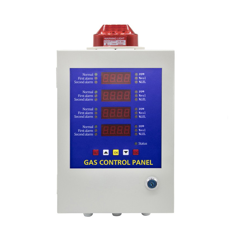
A ready indication on a burner panel has meaning because of the check behind it. A gas proving panel can confirm that designated shutoff valves met the conditions of a defined test. An ambient gas alarm controller reports what its detectors measured and can command a response. The two functions answer different questions about the same installation.
A record of the proving test, a record of an alarm, and evidence that a fan or valve moved each cover a different part of the system. The distinction becomes especially useful during commissioning, when a screen indication may look reassuring even though the corresponding field check is still outstanding.
Define the Boundary of the Test
A pressure-based gas proving panel evaluates a test space associated with automatic shutoff valves in a gas train. In one common design, the test assesses pressure behavior in the space between two valves during a defined interval. Excessive pressure change under the applicable conditions can indicate leakage across a shutoff valve. Failure can prevent startup in an appropriately integrated burner system.
Pressure is the evidence in that type of test. The controller interprets it against a particular test window and criterion. The valve command identifies the state requested by the control system, while the pressure response supplies evidence about how the isolated section behaved. A passing result establishes that the measured pressure change met the test criterion under the specified conditions.
A successful result applies to the tested valves, the test conditions, and the system’s ability to detect leakage under those conditions. Other parts of the installation, such as joints elsewhere in the pipework, fall outside that particular result. The scope matters just as much as the indication of a pass.
A gas detection control panel works from a different measurement. Its transmitters sample ambient gas at assigned positions, and the resulting concentrations describe conditions at those points. A detector in the room can register gas reaching its sensor, whereas a proving test uses information from the gas train. The specified measurement determines what the result can establish.
From a Detector Reading to an Alarm
The transmitter provides the input that lets a gas detection control panel show a concentration and evaluate the configured alarm limits. Each channel needs to correspond to the intended gas and location. The signal and the channel designation are both relevant when an operator has to identify which part of a plant has called for a response.
The Bosean BH-50 illustrates the concentration monitoring function. Standard versions are available with one, two, or four channels and accept 4–20 mA or RS485 transmitter signals as configured. The panel displays concentrations by channel and compares the received values with configured limits. Its integrated audible and visual indications can warn of an alarm condition.
The units and measurement range belong alongside the channel label in the project record. Those fields show what a displayed number means for the configured transmitter. During an acceptance check, the observed value and warning can then be matched with the intended detector and location, giving evidence that the signal reached the expected channel and was evaluated by the alarm logic.
Follow the Output to the Field Equipment
A relay command can be present even while the equipment it controls remains stopped. The relay from a gas detection control panel provides an output that an external circuit can use. Evidence of a fan turning, airflow reaching its destination, or a valve reaching a specified position comes from the connected equipment or its independent feedback.
The Bosean BH-50 has a normally open relay control terminal. In a system configured to use that contact for an exhaust command, a test can document that the alarm caused the intended contact to change. Confirmation of the exhaust response belongs in a separate field. The contact state alone describes an electrical event at the panel.
The separation is useful when a test stops partway through the chain. A displayed alarm with a confirmed relay change narrows the investigation to the downstream circuit or equipment, while a missing channel response sends the investigation back toward the input. Recording each observation gives maintenance staff a more precise starting point.
Document What the System Demonstrated
Acceptance records can show where the verification ended. A proving result belongs with the identified valves and applicable test conditions. A concentration alarm test can track the sensor response, the displayed channel, the alarm, the output, and the connected equipment’s response. The observations together show which parts of the design worked during the test. A results sheet that lists the expected indication beside the observed one also makes a partial check visible during handover.
A specification for a gas proving panel can identify the required valve test and the permissive it supplies to the burner control. The concentration alarm specification can separately identify the transmitters, channel indications, and relay functions. In a project using the Bosean controller for the latter, the documentation can make each assignment clear to the installer and the operator.
Any missing observation belongs in the handover record alongside the evidence still needed. A valve proving result and an alarm response both have value when their scope is clear. Each item can close at the point where the test produced a documented measurement or a confirmed field response.
SEO Title: Gas Proving Panels: Valve Tests and Alarm Checks
Meta Description: Learn what gas proving panels verify in valve tests, how gas detection controllers respond to readings and what to record after checking field outputs.