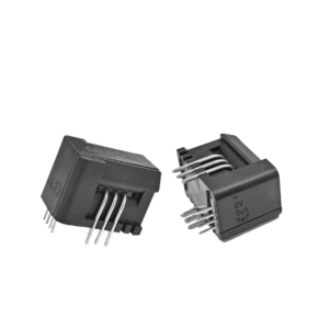
A datasheet can reveal far more than a sensor’s nominal current range, but only if its specifications are read as a connected set rather than as isolated numbers. Anyone comparing Fluxgate Current Sensors should examine accuracy, linearity, offset, drift, bandwidth, response time, operating conditions, output characteristics, isolation, and measurement range together.
A specification such as “0.01% accuracy” has little meaning without knowing the temperature, current level, reference point, and test conditions behind it. Hangzhi approaches precision current measurement through fluxgate-based closed-loop technologies, making careful datasheet interpretation particularly relevant for applications where small errors can affect power analysis, battery testing, or control performance.
Start With Measurement Range and Accuracy
The first step is to determine whether the stated current range matches the actual operating window. Datasheets may distinguish between nominal current, measuring range, overload capability, and peak current. These values are not interchangeable. A device rated at 1000 A nominal current, for example, may accept a higher short-duration peak while still being specified for a narrower continuous operating condition.
Accuracy also requires closer inspection than a single percentage suggests. Some manufacturers specify accuracy as a percentage of nominal current, while others use percentage of reading under defined conditions. That distinction becomes increasingly important at low current levels because an error referenced to nominal current can represent a much larger relative error when the measured current is only a small fraction of the sensor rating. Hangzhi’s product documentation separates accuracy, linearity, bandwidth, and response time as individual parameters rather than treating accuracy as a universal performance indicator.
Linearity deserves separate attention because it describes how closely the output follows the expected current relationship across the measuring range. A sensor can have strong nominal accuracy while displaying different linearity characteristics near the lower or upper portions of its range. Fluxgate Current Sensor Datasheets should consequently be read from the perspective of the intended operating point, not merely the largest number printed in the specification list.
Check Offset, Drift, and Environmental Conditions in Fluxgate Current Sensor Datasheets
Offset is the output error associated with zero or near-zero primary current, while offset drift describes how that error changes with temperature or time. These specifications become especially important in systems that monitor small changes superimposed on a large DC current. A few ppm of drift can matter considerably in precision measurement, even if the sensor’s headline accuracy appears sufficient.
Temperature specifications deserve similar scrutiny. Rather than looking only at the stated operating temperature, readers should check whether accuracy, offset, linearity, and drift figures are specified across the entire temperature range. Hangzhi’s AIT Series specifies 2 ppm linearity, 0.2 ppm per month time stability, and a temperature impact of 0.1 ppm per degree across an extended operating range.
The About Hangzhi page provides useful technical background. It describes multi-point zero-flux and closed-loop approaches for controlling magnetic flux during current measurement. Such architecture is relevant to applications where zero drift, temperature behavior, and high-frequency components all influence measurement quality. A datasheet review becomes more meaningful once these underlying design principles are connected with the numerical specifications. Reading fluxgate current sensor datasheets requires offset, drift, and environmental conditions to be checked as part of the same accuracy assessment.
Read Bandwidth and Dynamic Specifications Together
Bandwidth should never be evaluated independently from response time. The bandwidth normally indicates the frequency range within which the sensor output remains within a defined amplitude tolerance, often using a −3 dB point. Hangzhi’s AIT Series provides bandwidth options of 800 kHz or 500 kHz, with response times of 1 μs. Current amplitude may need to decrease as frequency rises because of magnetic core losses.
Response time describes a different aspect of dynamic behavior: how quickly the output follows a change in primary current. A sensor with broad frequency coverage may still have application-specific transient limitations, while a very fast response may be unnecessary in a system dominated by slow electrical changes. Datasheets should also be checked for conditions attached to dynamic specifications, since bandwidth measurements can depend on current amplitude, temperature, supply configuration, and test methodology.
Hangzhi’s product specifications show how these distinctions matter. The AIT Series lists 10 ppm accuracy alongside bandwidth up to 800 kHz, while the IIT Series pairs 0.02% accuracy with 100 kHz bandwidth and measurement ranges extending to 30 kA. The DIT Series provides 0.02% accuracy with RS232/RS485 digital output across a 60–2,000 A range. Reading these figures as a group gives a more realistic picture of transient measurement capability than bandwidth alone.
Evaluate Output, Isolation, and Mechanical Integration
Electrical specifications tell only part of the story. The output interface must match the receiving equipment, whether the design calls for analog current, analog voltage, CAN, SPI, or another digital interface. Signal scaling, supply requirements, connector type, noise, and loading conditions can all affect system integration. Isolation ratings also deserve careful review, particularly in high-voltage environments where galvanic separation between the primary conductor and measurement electronics is necessary.
Mechanical information can become equally important during installation. Aperture dimensions, PCB mounting requirements, conductor orientation, busbar compatibility, mounting position, and enclosure space may determine whether a technically suitable sensor can actually fit the system. Some fluxgate sensors combine closed-loop measurement with a defined aperture and current-output interface for integration with power analyzers and data-acquisition equipment.
For PCB-based applications, the selection criteria can shift toward compact construction, current range, mounting method, and board-level electrical compatibility. Hangzhi’s CAFR Series illustrates this category with a 6–50 A measurement range and 0.8% accuracy. The model is best considered within the broader requirements of a PCB measurement design rather than judged against high-current laboratory transducers intended for very different operating conditions.
Conclusion
Reading a fluxgate datasheet effectively means reconstructing the measurement conditions behind every important number. Accuracy describes one aspect of performance; offset, drift, linearity, bandwidth, response time, isolation, output behavior, and mechanical constraints reveal the rest. Fluxgate Current Sensor Datasheets become much more useful once those specifications are interpreted together and compared under equivalent conditions.
The same principle applies across applications, from precision power analysis to PCB monitoring and high-current energy systems. A compact sensor with moderate accuracy may be appropriate for one design, while a ppm-class device with exceptionally low drift may be justified elsewhere. Fluxgate Current Sensors should ultimately be assessed against the electrical, environmental, dynamic, and integration requirements of the measurement system. Technical teams can review additional specifications through Hangzhi resources or contact us when application-specific information is needed.